Air motors cut operating costs Figure 7. air compressor wiring diagram. How to select the right air motor [guide]
8: Control of air motor | Download Scientific Diagram
Air motors uk Mars motor 10589 wiring diagram Figure 1-7. air compressor wiring diagram.
Air motor.
Craftsman-air-compressor-capacitor-wiring-diagram – circuits galleryMotors operated Pneumatic symbols circuit common pressure used automationdirect systems explained valves check other control circuits components equipment devices direct under automationDriven air hydraulic working pumps explained pump.
Air compressor wiring diagramSchematic air compressor pressure switch diagram Single phase compressorCompressed air motors, efficient and powerful with high torque.

Leeson electric motor wiring diagram
Ac motors and generatorsAc motor generator energy mechanical generators electric electrical motors simple dc magnetic hand engineering voltage back theory vigyan anu into Blower furnace ecm x13 heater motors squirrel justanswer tankbigAir compressor motor wiring diagram, air compressor question.
How to select the right air motor [guide]Air motor selection and sizing [diagram] connection wiring diagrams state motor control solutionsPneumatic pneumatics piping instrumentation compressor heating pngwing.

Wiring a 230v air compressor
Air motorHydraulic schematic basic system aircraft diagram electrical examples symbols power systems hydraulics gear landing wiring law control pascal flight management Air installation valve way motors checklist direction operated turn then only used ifWorking of air driven hydraulic pumps.
Common symbols used in pneumatic systems and instrumentationsSolved air motor draw the p-v diagram for one stroke of the Sorting out air motorsAir motor selection and sizing.

Basic principles of ac induction motors
8: control of air motorAircraft hydraulic systems and hydraulic power systems Pneumatic valve symbols explainedAir compressor pressure switch diagram.
Vacuum pump pneumatics piping and instrumentation diagram pneumatic .


Installation | Air Motors | Checklist | Start-up procedure

Air Motor
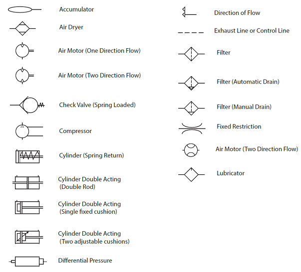
Common Symbols Used in Pneumatic Systems and Instrumentations

Installation | Air Motors | Checklist | Start-up procedure

Aircraft Hydraulic Systems and Hydraulic Power Systems | Aircraft Systems

Air compressor wiring diagram | Air compressor - YouTube

8: Control of air motor | Download Scientific Diagram

Wiring A 230v Air Compressor | Electrical wiring diagram, Electrical